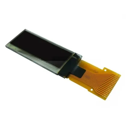
ND042PHM7240-A01 | 0.42-Inch White PMOLED Display with 72 × 40 Resolution
The ND042PHM7240-A01 is a white 0.42-inch transmissive PMOLED display module with 72 × 40 resolution. It uses an SSD1315 controller and an IIC / I2C serial interface through a 16-pin connector. Listed performance includes 430 cd/m² luminance and a 2.8 V supply.
The standard listed configuration has no touchscreen. The module has a -40°C to 70°C operating temperature range and a -40°C to 85°C storage temperature range.
Integration Notes
Before design-in, confirm the host IIC / I2C signalling and initialisation sequence, pin assignment, connector orientation, supply requirements, mechanical dimensions and optical requirements against the applicable drawing. This module is not presented as a universal drop-in replacement.
Typical Applications
The compact format can suit status readouts, handheld instrumentation, wearable-device concepts and embedded user interfaces where the display size, interface and mechanical envelope match the project requirements.
Request Technical Details
For a technical check or quotation, share the required quantity, host controller or equipment model, interface requirements and mechanical drawing.
General Specifications
| Part No.: | ND042PHM7240-A01 |
| Size: | 0.42 inch |
| Display Format: | 72×40 Resolution |
| Display Type: | PMOLED Display |
| Display Mode: | Transmissive |
| Touchscreen: | No (Optional with Yes) |
| Optimal View: | 160 |
| Outline Dimension: | 12x11x1.26(mm) |
| Active Area: | 9.196×5.18(mm) |
| Supply Voltage: | 2.8V |
| Luminance | 430cd/m² |
| Interface: | IIC |
| Connection Type: | 16pin connector |
| Controller: | SSD1315 |
| Compatibility: | Arduino and similar development boards |
| Operating Temperature: | -40°C ~ 70°C |
| Storage Temperature: | -40°C ~ 85°C |
| Mount Frame: | None |
Display Drawing

Interface Definition
| NO. | Symbol | Function |
|---|---|---|
| 1 | C2P | Positive Terminal of the Flying Inverting Capacitor Negative Terminal of the Flying Boost Capacitor The charge-pump capacitors are required between the terminals. They must be floated when the converter is not used. |
| 2 | C2N | |
| 3 | C1P | |
| 4 | C1N | |
| 5 | VBAT | Power Supply for DC/DC Converter Circuit This is the power supply pin for the internal buffer of the DC/DC voltage |
| 6 | VSS | Ground of Logic Circuit This is a ground pin. It acts as a reference for the logic pins. |
| 7 | VDD | Power Supply for Logic This is a voltage supply pin. It must be connected to external source. |
| 8 | BS1 | ![]() |
| 9 | CS# | Chip Select This pin is the chip select input. The chip is enabled for MCU communication |
| 10 | RES# | Power Reset for Controller and Driver This pin is reset signal input. |
| 11 | D/C# | Data/Command Control This pin is Data/Command control pin. |
| 12 | D0 | When serial interface mode is selected, D2 should be either tied LOW or tied together with D1 as the serial data input: SDIN, and D0 will be the serial clock input: SCLK. When I2 C mode is selected, D2, D1 should be tied together and serve as SDAout, SDAin in application and D0 is the serial clock input, SCL |
| 13 | D1 | |
| 14 | D2 | |
| 15 | VCOMH | Voltage Output High Level for COM Signal This pin is the input pin for the voltage output high level for COM signals. |
| 16 | VCC | Power Supply for OEL Panel This is the most positive voltage supply pin of the chip. |
Custom 0.42'' PMOLED display
We offer custom 0.42'' PMOLED display modules, allowing you to adjust key specifications such as resolution, brightness, and interface options. Our solutions also include personalized connector placements and seamless integration with platforms like Arduino, ensuring optimal system performance.
Custom OLED Display

Design the ideal 0.42” OLED display with fully customizable sizes, resolutions, and configurations, tailored to meet your unique design and application requirements.
Custom OLED Interfaces

Customizable cable lengths and connector configurations for 0.42” OLED modules ensure precise integration with your system, offering reliable performance and flawless display alignment.
0.42' OLED PCB Design

Optimized PCB design for 0.42” OLED modules ensures efficient power distribution and signal integrity, providing stable, high-quality display performance in compact systems.
Different Color Options

Choose from a range of color options for 0.42” OLED modules, offering tailored visual experiences and increased design flexibility to perfectly fit your project or application.


Reviews
There are no reviews yet.