

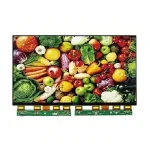


Mechanical Drawing & Interface Definition
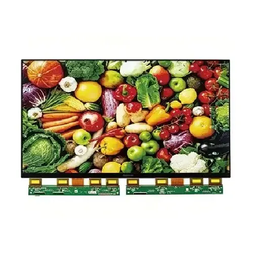
Model: ND320EPN25601440-A01
Download Center Contact an Engineer
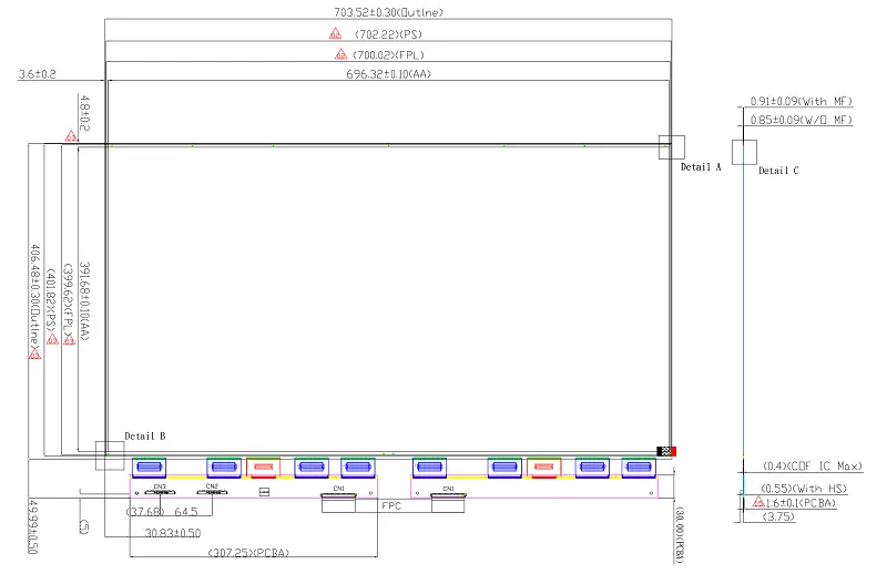
PIN Description
CON2 — Signal Connector (51PIN)
| Pin No. | Symbol | Description |
|---|---|---|
| 01 | R-CS0 | Right-half serial chip select. (I/O: I/O) |
| 02 | R-CS1 | Right-half serial chip select. (I/O: I/O) |
| 03 | R-CS2 | Right-half serial chip select. (I/O: I/O) |
| 04 | R-CS3 | Right-half serial chip select. (I/O: I/O) |
| 05 | R-SCL | Right-half serial clock. (I/O: I/O) |
| 06 | R-D_CX | 4-wire SPI command/data selection. (I/O: I/O) |
| 07 | R-SI0 | SDA / MOSI; quad data input. (I/O: I/O) |
| 08 | R-SI | MISO; quad data input. (I/O: I/O) |
| 09 | R-SI2 | Quad data input. (I/O: I/O) |
| 10 | R-SI3 | Quad data input. (I/O: I/O) |
| 11 | NC | Leave unconnected. (I/O: —) |
| 12 | NC | Leave unconnected. (I/O: —) |
| 13 | NC | Leave unconnected. (I/O: —) |
| 14 | NC | Leave unconnected. (I/O: —) |
| 15 | L-CS0 | Left-half serial chip select. (I/O: I/O) |
| 16 | L-CS1 | Left-half serial chip select. (I/O: I/O) |
| 17 | L-CS2 | Left-half serial chip select. (I/O: I/O) |
| 18 | L-CS3 | Left-half serial chip select. (I/O: I/O) |
| 19 | L-SCL | Left-half serial clock. (I/O: I/O) |
| 20 | L-D_CX | 4-wire SPI command/data selection. (I/O: I/O) |
| 21 | L-SI0 | SDA / MOSI; quad data input. (I/O: I/O) |
| 22 | L-SI1 | MISO; quad data input. (I/O: I/O) |
| 23 | L-SI2 | Quad data input. (I/O: I/O) |
| 24 | L-SI3 | Quad data input. (I/O: I/O) |
| 25 | NC | Leave unconnected. (I/O: —) |
| 26 | NC | Leave unconnected. (I/O: —) |
| 27 | NC | Leave unconnected. (I/O: —) |
| 28 | RST_N | Global reset; low = reset. (I/O: I/O) |
| 29 | BUSY_N | 0 = busy; 1 = not busy. (I/O: I/O) |
| 30 | CL | Master clock output / slave clock input; not the SPI clock. (I/O: I/O) |
| 31 | NC | Leave unconnected. (I/O: —) |
| 32 | NC | Leave unconnected. (I/O: —) |
| 33 | NC | Leave unconnected. (I/O: —) |
| 34 | NC | Leave unconnected. (I/O: —) |
| 35 | NC | Leave unconnected. (I/O: —) |
| 36 | NC | Leave unconnected. (I/O: —) |
| 37 | NC | Leave unconnected. (I/O: —) |
| 38 | NC | Leave unconnected. (I/O: —) |
| 39 | NC | Leave unconnected. (I/O: —) |
| 40 | NC | Leave unconnected. (I/O: —) |
| 41 | NC | Leave unconnected. (I/O: —) |
| 42 | NC | Leave unconnected. (I/O: —) |
| 43 | TSCL | External temperature-sensor I2C clock. (I/O: —) |
| 44 | TSDA | External temperature-sensor I2C data. (I/O: —) |
| 45 | NC | Leave unconnected. (I/O: —) |
| 46 | NC | Leave unconnected. (I/O: —) |
| 47 | NC | Leave unconnected. (I/O: —) |
| 48 | NC | Leave unconnected. (I/O: —) |
| 49 | NC | Leave unconnected. (I/O: —) |
| 50 | NC | Leave unconnected. (I/O: —) |
| 51 | NC | Leave unconnected. (I/O: —) |
CON3 — Power Connector (51PIN)
| Pin No. | Symbol | Description |
|---|---|---|
| 01 | VSPHI | Positive source-driver supply. (I/O: P) |
| 02 | VSPHI | Positive source-driver supply. (I/O: P) |
| 03 | VSPHI | Positive source-driver supply. (I/O: P) |
| 04 | VSPLI | Positive source-driver supply. (I/O: P) |
| 05 | VSPLI | Positive source-driver supply. (I/O: P) |
| 06 | VSPLI | Positive source-driver supply. (I/O: P) |
| 07 | VSPL2I | Positive source-driver supply. (I/O: P) |
| 08 | VSPL2I | Positive source-driver supply. (I/O: P) |
| 09 | VSPL2I | Positive source-driver supply. (I/O: P) |
| 10 | VSNHI | Negative source-driver supply. (I/O: P) |
| 11 | VSNHI | Negative source-driver supply. (I/O: P) |
| 12 | VSNHI | Negative source-driver supply. (I/O: P) |
| 13 | VSNLI | Negative source-driver supply. (I/O: P) |
| 14 | VSNLI | Negative source-driver supply. (I/O: P) |
| 15 | VSNLI | Negative source-driver supply. (I/O: P) |
| 16 | VSNL2I | Negative source-driver supply. (I/O: P) |
| 17 | VSNL2I | Negative source-driver supply. (I/O: P) |
| 18 | VSNL2I | Negative source-driver supply. (I/O: P) |
| 19 | VPP | Source-driver OTP supply. (I/O: P) |
| 20 | VPP | Source-driver OTP supply. (I/O: P) |
| 21 | GND | Ground. (I/O: G) |
| 22 | GND | Ground. (I/O: G) |
| 23 | VGH | Positive gate-driver supply. (I/O: P) |
| 24 | VGH | Positive gate-driver supply. (I/O: P) |
| 25 | AVDD | DC/DC power input. (I/O: P) |
| 26 | AVDD | DC/DC power input. (I/O: P) |
| 27 | AVDD | DC/DC power input. (I/O: P) |
| 28 | VDD | Source-driver analog / digital supply. (I/O: P) |
| 29 | VDD | Source-driver analog / digital supply. (I/O: P) |
| 30 | VCC | Source-driver oscillator common voltage. (I/O: P) |
| 31 | VCC | Source-driver oscillator common voltage. (I/O: P) |
| 32 | VDDN | Negative analog supply. (I/O: P) |
| 33 | VDDN | Negative analog supply. (I/O: P) |
| 34 | VDDN | Negative analog supply. (I/O: P) |
| 35 | VGL | Negative gate-driver supply. (I/O: P) |
| 36 | VGL | Negative gate-driver supply. (I/O: P) |
| 37 | VDDP | Positive analog supply. (I/O: P) |
| 38 | VDDP | Positive analog supply. (I/O: P) |
| 39 | VDDP | Positive analog supply. (I/O: P) |
| 40 | Boder | Border voltage-check output. (I/O: P) |
| 41 | Boder | Border voltage-check output. (I/O: P) |
| 42 | VCOMBD | Border buffer output; use 0.47 µF stabilization per application circuit. (I/O: P) |
| 43 | VCOMBD | Border buffer output; use 0.47 µF stabilization per application circuit. (I/O: P) |
| 44 | VNCP-3P5V | Negative analog supply for TFT VCOM. (I/O: P) |
| 45 | VNCP-3P5V | Negative analog supply for TFT VCOM. (I/O: P) |
| 46 | VBB-3P5V | Negative analog supply for TFT VCOM. (I/O: P) |
| 47 | VBB-3P5V | Negative analog supply for TFT VCOM. (I/O: P) |
| 48 | TFT-VCOM | Common voltage. (I/O: P) |
| 49 | TFT-VCOM | Common voltage. (I/O: P) |
| 50 | FPL-VCOM | Common voltage. (I/O: P) |
| 51 | FPL-VCOM | Common voltage. (I/O: P) |
Connector: P-TWO 187059-51221 compatible. D_CX: low = command and high = data in 4-wire SPI; tie to GND in 3-wire or standard 4-wire mode. NC pins remain unconnected. “R-SI” and “Boder” retain the signal names in the specification; “Boder” means Border. CON3 requires the specified power rails and sequencing; a single 3.3 V supply is insufficient.
Sample Ordering & Delivery
Evaluate ND320EPN25601440-A01 32.0-inch engineering samples before integration. Shipping is charged separately; import duties and taxes are excluded. Estimated delivery includes preparation. Confirm final terms before payment.
Sample MOQ
2 pcs per modelMinimum 2 pcs per model.
Preparation Time
4 daysAfter order and payment confirmation.
Standard Delivery
Shipping Fee
Transit Time: ~11 days
Total Time: ~15 days
Express Delivery
Shipping Fee
Transit Time: ~4 days
Total Time: ~8 days

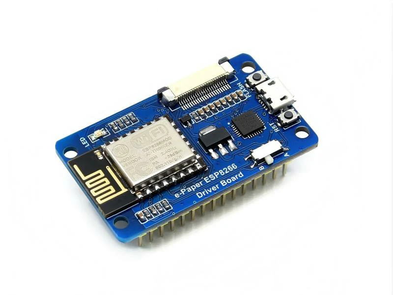
Matching Driver Board
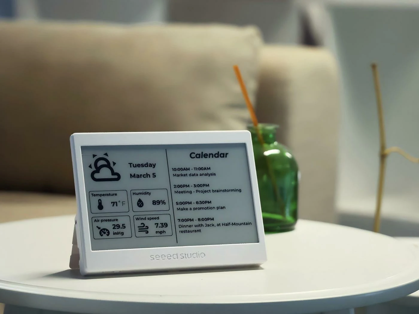
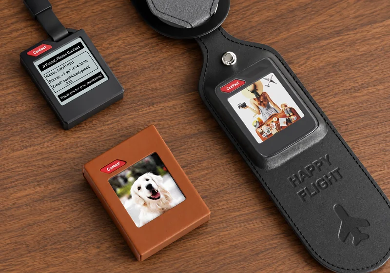
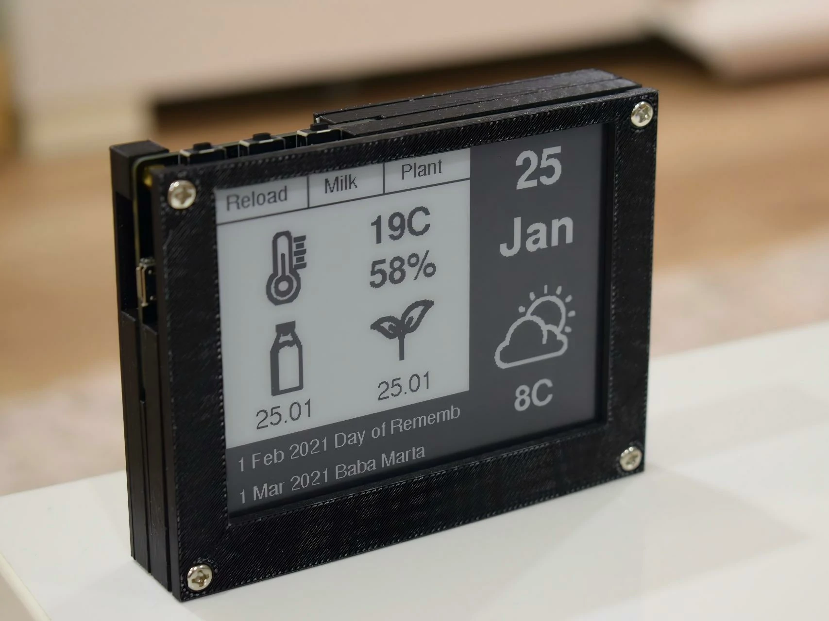
ND320EPN25601440-A01 requires an external TCON; the recommended OK-DEV03A evaluation board is a separate accessory. Review CON2 signal wiring and CON3 power rails, supply sequencing, initialization and waveform configuration. The panel supports SPI with single, dual and quad data transfer; quad mode applies to R10h image-data bytes. Confirm image conversion, host firmware, controller availability and package contents for evaluation.
Recommended evaluation board: OK-DEV03A. The ESP32-S3-based board is intended for 31.5-inch Spectra 6 display development and evaluation. Reference features include Wi-Fi, Bluetooth and USB Type-C; the listed power input is 12 V DC. Confirm the board configuration, power connection and supported firmware for your project.
The OK-DEV03A is a separate accessory. CON2 carries panel signals and CON3 carries the required power rails. The module operating range remains 0°C to +50°C.
Quality & Compliance Support
We provide quality and compliance documentation for qualified OEM projects
based on the selected module, BOM and manufacturing configuration.
RoHS
EU RoHS compliant materials and process control
REACH
Support REACH regulation compliance
Reliability Testing
Environmental & mechanical reliability testing reports
ESD Control
ESD protection design and testing capability
Quality System
Manufactured under a certified quality management system
Documentation availability and scope are confirmed according to the selected module, BOM, manufacturing source and project requirements.